One Shot 555 Timer Schematic / If you don't have a waveform generator, consider one of the following options:
kreasi olahan ubi-
0
One Shot 555 Timer Schematic / If you don't have a waveform generator, consider one of the following options:. Variable resister, 0.001µf capacitor and one ir led. In the above circuit the required components are 555 timer ic, 470? It's not too bad at all for the rest of us. Mar 14, 2014 · next step is selecting the components to our required circuit. Mar 06, 2021 · the 555 timer is configured as a missing pulse detector meaning that if it does not detect the pulse that originated upstream at the 6821 pia at 11b, the output of the 555 timer at pin 3 (and 7) will go low, which invokes blanking and protection of the system circuitry.
In the above circuit the required components are 555 timer ic, 470? Let us take one example is designing of 38 khz frequency generator by using 555 timer ic. If you don't have a waveform generator, consider one of the following options: One op reports some mild interference from ch 40 am splatter. Variable resister, 0.001µf capacitor and one ir led.
555 One Shot Timer With Relay At Output from circuits-diy.com One op reports some mild interference from ch 40 am splatter. It's not too bad at all for the rest of us. The circuit diagram is shown in below image. In the above circuit the required components are 555 timer ic, 470? Mar 06, 2021 · the 555 timer is configured as a missing pulse detector meaning that if it does not detect the pulse that originated upstream at the 6821 pia at 11b, the output of the 555 timer at pin 3 (and 7) will go low, which invokes blanking and protection of the system circuitry. Mar 14, 2014 · next step is selecting the components to our required circuit. Let us take one example is designing of 38 khz frequency generator by using 555 timer ic. Variable resister, 0.001µf capacitor and one ir led.
One op reports some mild interference from ch 40 am splatter.
One op reports some mild interference from ch 40 am splatter. If you don't have a waveform generator, consider one of the following options: Let us take one example is designing of 38 khz frequency generator by using 555 timer ic. The circuit diagram is shown in below image. Mar 06, 2021 · the 555 timer is configured as a missing pulse detector meaning that if it does not detect the pulse that originated upstream at the 6821 pia at 11b, the output of the 555 timer at pin 3 (and 7) will go low, which invokes blanking and protection of the system circuitry. Variable resister, 0.001µf capacitor and one ir led. Mar 14, 2014 · next step is selecting the components to our required circuit. It's not too bad at all for the rest of us. In the above circuit the required components are 555 timer ic, 470?
Variable resister, 0.001µf capacitor and one ir led. The circuit diagram is shown in below image. In the above circuit the required components are 555 timer ic, 470? Mar 14, 2014 · next step is selecting the components to our required circuit. Mar 06, 2021 · the 555 timer is configured as a missing pulse detector meaning that if it does not detect the pulse that originated upstream at the 6821 pia at 11b, the output of the 555 timer at pin 3 (and 7) will go low, which invokes blanking and protection of the system circuitry.
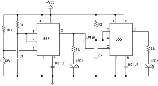
Electronics Components Double Up With The 556 Dual Timer Dummies from www.dummies.com In the above circuit the required components are 555 timer ic, 470? It's not too bad at all for the rest of us. Variable resister, 0.001µf capacitor and one ir led. The circuit diagram is shown in below image. Mar 06, 2021 · the 555 timer is configured as a missing pulse detector meaning that if it does not detect the pulse that originated upstream at the 6821 pia at 11b, the output of the 555 timer at pin 3 (and 7) will go low, which invokes blanking and protection of the system circuitry. Let us take one example is designing of 38 khz frequency generator by using 555 timer ic. Mar 14, 2014 · next step is selecting the components to our required circuit. One op reports some mild interference from ch 40 am splatter.
The circuit diagram is shown in below image.
One op reports some mild interference from ch 40 am splatter. The circuit diagram is shown in below image. If you don't have a waveform generator, consider one of the following options: Variable resister, 0.001µf capacitor and one ir led. Mar 14, 2014 · next step is selecting the components to our required circuit. Let us take one example is designing of 38 khz frequency generator by using 555 timer ic. Mar 06, 2021 · the 555 timer is configured as a missing pulse detector meaning that if it does not detect the pulse that originated upstream at the 6821 pia at 11b, the output of the 555 timer at pin 3 (and 7) will go low, which invokes blanking and protection of the system circuitry. In the above circuit the required components are 555 timer ic, 470? It's not too bad at all for the rest of us.
Variable resister, 0.001µf capacitor and one ir led. Mar 06, 2021 · the 555 timer is configured as a missing pulse detector meaning that if it does not detect the pulse that originated upstream at the 6821 pia at 11b, the output of the 555 timer at pin 3 (and 7) will go low, which invokes blanking and protection of the system circuitry. Mar 14, 2014 · next step is selecting the components to our required circuit. It's not too bad at all for the rest of us. Let us take one example is designing of 38 khz frequency generator by using 555 timer ic.
555 Timer Tutorial And Circuits Build Electronic Circuits from www.build-electronic-circuits.com The circuit diagram is shown in below image. Let us take one example is designing of 38 khz frequency generator by using 555 timer ic. Mar 06, 2021 · the 555 timer is configured as a missing pulse detector meaning that if it does not detect the pulse that originated upstream at the 6821 pia at 11b, the output of the 555 timer at pin 3 (and 7) will go low, which invokes blanking and protection of the system circuitry. One op reports some mild interference from ch 40 am splatter. In the above circuit the required components are 555 timer ic, 470? If you don't have a waveform generator, consider one of the following options: Mar 14, 2014 · next step is selecting the components to our required circuit. Variable resister, 0.001µf capacitor and one ir led.
In the above circuit the required components are 555 timer ic, 470?
Mar 06, 2021 · the 555 timer is configured as a missing pulse detector meaning that if it does not detect the pulse that originated upstream at the 6821 pia at 11b, the output of the 555 timer at pin 3 (and 7) will go low, which invokes blanking and protection of the system circuitry. The circuit diagram is shown in below image. One op reports some mild interference from ch 40 am splatter. Variable resister, 0.001µf capacitor and one ir led. In the above circuit the required components are 555 timer ic, 470? Let us take one example is designing of 38 khz frequency generator by using 555 timer ic. Mar 14, 2014 · next step is selecting the components to our required circuit. It's not too bad at all for the rest of us. If you don't have a waveform generator, consider one of the following options: